Archive for December, 2011

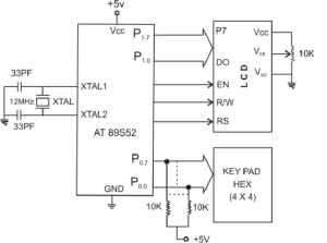
This program can show your desired text message in LCD screen.The application of this field is vast.This project can be used for customer care,for lighting,for publish a notice or any other application.This is very simple application of micro-controller and cost is very low.The main component of this project is only a micro-controller .So keep enjoy it….

Program Source Code
*********************************************************
#include <REG52.H>
sbit RS = P2∧0; // Control signal RESET of the LCD connected
to pin P2.0
sbit RW = P2∧1; // Write (RW) Signal pin connected to pin P2.1
sbit EN = P2∧2; // Enable (EN) LCD control signal connected to
pin P2.2
int i;
void delay(void); // Delay function
void INIT(void); // Function for the commands to Initialization of
the LCD
void ENABLE(void); // Function for the commands to enable the LCD
void LINE(int); /∗ Function for the commands to choose the line for
displaying the characters on the LCD ∗/
void LINE(int i) // start of LINE function
{ if (i==1)
{RS=0; // first make the reset signal low
RW=0; // make RW low to give commands to the LCD
P1=0x80; // force cursor to beginning of the first line
ENABLE(); // enable the LCD
RS=1;
}else
{RS=0;
RW=0;
P1=0xC0; // force cursor to beginning of the second line
ENABLE();
RS=1;
}
}

void delay() // Invoking the delay function.
{int j;
for (j=0;j<10;j++)
{for (i=0;i<100;i++);
}}
void ENABLE(void) // Invoking the enable function
{ EN=1; // Give high to low pulse to Enable the LCD.
delay();
EN=0;
delay();
}
void INIT(void) // Initialization of the LCD by giving the proper
commands.
{ RS=0;
RW=0;
EN=0;
P1 = 0x38; // 2 lines and 5∗7 matrix LCD.
ENABLE();
ENABLE();
ENABLE();
ENABLE();
P1 = 0x06; //Shift cursor to left
ENABLE();
P1 = 0x0E; // Display ON, Cursor Blinking
ENABLE();
P1 = 0x01; // Clear display Screen.
ENABLE();
}
void main (void)
{
char code dis[] = “We Thank Springer Publishers”;
char code dis2[] = “From Authors”; // Array of characters
to be display.

char ∗p; // Pointer to point the data in the array.
int j,x;
while(1)
{for (x=1;x<3;x++)
{
INIT();
LINE(1); // Display on the line 1 of the LCD.
if (x==1)
{p=&dis; // point the character address from the array “dis” where
it is stored.
}else
{p=&dis2; // Point the Character address from the “dis2” where it
is stored/
}for (j=0;j>8;j++){ P1= ∗p++; // Increment the pointer by 1.
ENABLE();
} LINE(2); // Display the second array on the second line on the LCD.
}}
}
*********************************************************
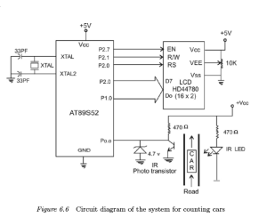
As shown in Figure IR transceiver is connected to the port pin P0.0 (sensor) through which the number of cars are counted as they pass through the passage and interrupt the IR link. The count is displayed on the LCD connected to port P1. The system is able to count the cars maximum up to 9999.This range can be increased using some modification of programming and circuit diagram connection.The modification is very easy if you understand the whole programming.So try it.This is a good project and application is huge cost is less.Again this can be used to count the people or visitor in a room or shopping complex or any company,industry….

Circuit diagram of the system for counting cars

Circuit diagram of the system for counting cars

Program Source Code
*********************************************************
#include <REG52.H>/*header file include*/
#include <stdio.h>
sbit sensor= P0∧0;
sbit RS = P2∧0;
sbit RW = P2∧1;
sbit EL = P2∧2;
unsigned int unit, ten, hundred, tenth, count;

void delay(int);
void INIT(void);
void ENABLE(void);
void LINE(int);
int updatecount(void); /∗ Function for update the count after passing
the car through the passage∗/
int updatecount()
{if (sensor==1) /∗ When the input pin detects the pulse increment
the count by one otherwise keep it as it
was∗/
{count=count+1; // increment count by 1
}else
{count=count+0; // keep count unchanged
}return(count); // returns the updated count value for next reference
}void LINE(int i) /∗ function to define the display characters on LCD
on specified line ∗/
{ if (i==1)
{RS=0;
RW=0;
P1=0x80; // Force cursor to beginning of the first line
ENABLE(); // Enable LCD
RS=1; // Reset the LCD
}else
{RS=0;
RW=0;
P1=0xC0; // Force cursor to beginning of the second line
ENABLE();
RS=1;
}
}

void delay(int k) // Delay function
{int i,j;
for (j=0;j<k+1;j++) // Delay loop
{for (i=0;i<10000;i++);
}}
void ENABLE(void) // Function to Enable the LCD
{EL=1; // Give high to low pulse to enable pin of
the LCD
delay(1);
EL=0;
delay(1);
}
void INIT(void) // Function to Initialize the LCD
{ RS=0;
RW=0;
EL=0;
P1 = 0x38; // LCD of 2 lines and 5×7 matrix
ENABLE();
ENABLE();
ENABLE();
ENABLE();
P1 = 0x06; // Shift cursor to right
ENABLE();
P1 = 0x0E; // Display on, cursor blinking
ENABLE();
P1 = 0x01;
ENABLE();
}
void main (void)
{int count=0;

int k;
char ∗p;
char array[ ]=“No of Cars=”; /∗ Array to display the characters “No
of Cars=” on the LCD ∗/
INIT();
while(1)
{count= updatecount(); /∗ Assign the returned new value to update the
count ∗/
p=&array; /∗ Points the next location on the LCD to
display the character∗/
for (k=0;k<17;k++)
{if (k==0)
LINE(1);
P1= ∗p++; // Increment the pointer
ENABLE();
LINE(2);
unit =(count%10);
ten=(count/10)%10; /∗ Display no of cars and the count on LCD
on respective decimal position. The character
to display should be in ASCII form.∗/
hundred=(count/100)%10;
tenth=(count/1000);
P1= (tenth+0x30); // Send the ASCII data to LCD
ENABLE();
P1= (hundred+0x30);
ENABLE();
P1= (ten+0x30);
ENABLE();
P1= (unit+0x30);
ENABLE();
}}
}

*********************************************************
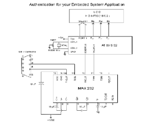
The  Figure is used for this application. The program prompts the user to enter his user ID by displaying a message “LOGIN” on the LCD. The user is expected to enter his ID using the PC keyboard. Then the program displays a message “password” on the LCD to prompt the user to enter the password. After entering the password, the program will check whether the entered information is correct or not. The system can also be used for cabinet lock-up or for any keyboardbased security implementation.This project is very useful to control the automatic door open with authentication,window open,or any security system.so try it now…

Authentication for Your Embedded System Application

Authentication for Your Embedded System Application

Program Source Code
******************************************************
#include <REG52.H>
#include <stdio.h>
sbit RS = P2∧0;
sbit RW = P2∧1;
sbit EL = P2∧2;
void INITt ();
void delay(int);
void INIT(void);
void ENABLE(void);
void LINE(int);
char array[]=“LOGIN:”;
char pass[]=“EMBEDED”;
char Access[]=“CORRECT”;
char denied[]=“WRONG”;

void INITt() // function to Initialize the timer
{ TMOD=0x20;
TH1=0xFD;
SCON=0x50;
TR1=1;
}void LINE (int i) // Enable the line function
{if (i= =1)
{RS=0;
RW=0;
P1=0x80;
ENABLE();
RS=1;
} else
{RS=0;
RW=0;
P1=0xC0;
ENABLE();
RS=1;
}
}
void delay(int k) // invoking delay function
{int i,j;
for (j=0;j<k+1;j++)
{ for (i=0;i<10000;i++);
}
}
void ENABLE(void) // invoking the enable function
{EL=1;

delay(1);
EL=0;
delay(1);
}
void INIT(void) /∗initialization of LCD display∗/
{RS=0;
RW=0;
EL=0;
P1 = 0x38;
ENABLE();
ENABLE();
ENABLE();
ENABLE();
P1 = 0x06;
ENABLE();
P1 = 0x0E;
ENABLE();
P1 = 0x01;
ENABLE();
}
void main (void) // main function
{char b,var;
char ∗p;
int i,j,k;
while (1)
{INIT();
LINE (1);
for (b=0;b<8;b++)
{p=&array;
P1= ∗p++; /∗ increment the pointer and point the
data from the array ∗/
ENABLE ();
}

{INITt();
RI=0;
var=SBUF;
while(!RI);
RI=0;
while(1)
{for (i=0;i<8;i++)
{
if((pass[i])= =(var[i]))
for(j=0;j<8;j++)
{LINE(1);
p=&Access;
P1= ∗p++;
ENABLE();
}else
{LINE(1);
p=&denied;
P1= ∗p++;
ENABLE();
}
RS=0;
P1=0x01;
ENABLE();
RS=1;
}}
}}}
******************************************************
 

Designing a Wire Antenna for 2.4 GHz ISM Band Applications

Abstract:

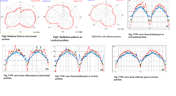
This work presents a free space wire antenna for the application of 2.45 GHz industrial, scientific, and medical (ISM) band applications. The designed antenna occupies 10 dB return loss bandwidth of 310 MHz (2320-2630 MHz) with VSWR less than 2 within the antenna bandwidth. The gain of the antenna over the antenna operating band is varies from 1.87-1.89. The characteristic impedance of the antenna is 51.44Ω at the operating frequency.

Introduction:

2.45 GHz ISM band frequency ranges from 2.4 GHz to 2.4835 GHz. Mobile Worldwide Interoperability for Microwave Access (Mobile WiMAX) or Fixed WiMAX operating bands are 2.3 GHz (2.3-2.4 GHz), 2.5 GHz (2.5-2.7 GHz), Wireless Local Area Network (WLAN) operating frequency range is 2.4-2.4835 GHz. On the other hand, Bluetooth operating frequency range is 2.4-2.4835 GHz.

   This band widely used for electronic news gathering and outside broadcast TV links in IEEE 802.11 ISM band. The designed antenna is a wire antenna of U shape. The radiation pattern of this antenna is suitable for electronic news gathering and outside broadcast TV links applications. Electronic news gathering and outside broadcast TV links are used across the UK to provide services ancillary to broadcasting. Most links tend to be used for comparatively short periods of time (hours), though some outside broadcast (OB) events may last for weeks. Within Uk there exists 15 channels of nominal bandwidth allocated for use temporary vedio links in the2390-2690Mhz band. Nine of these channels are used for ENG in London. In outside broadcasting such as formula 1 racing poleman camera is fixed point2.5Ghz. Pressure on the 2.4Ghz band from ENG/OB application will be farther exacerbated by the fact that total bandwidth available to satisfy user demand is likely to be reduced. Most specifically, the decision at WRC 2000 to allocate 2520-2670 MHz as future expansion spectrum for third generation mobile services is likely to intensify pressure on the 2390-2520 MHz band.

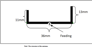
antenna structure

antenna structure

Simulation Results:

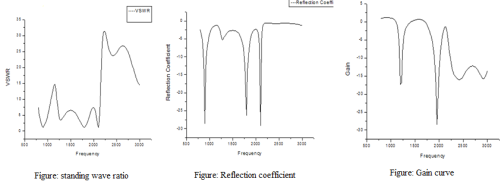
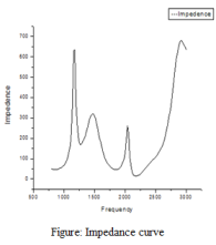
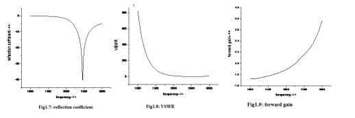
From the curve it is shown that the vswr of antenna is less than 2 from 2320-2630MHz range. At the operating frequency vswr is 1.05The shown the 10db bandwidth for a range 2320-2630 MHz  The maximum value of it is -35db and in the operating frequency it is -31.069db.In this curve the forward gain varies from 1.870-1.890 over the range. At the operating frequency the forward gain is 1.88.From the impedance curve it is shown that the characteristic impedance of the antenna varies from 45.05Ω-59.68Ω over the range. At the resonance frequency it is 51.44Ω. It is slightly high value from the standard value.

simulation result

simulation result

simulation result

simulation result

Experimental result:

experimental result

experimental result

Course Title: Antenna Engineering LaboratoryCourse No: ECE-3208

Date of Submission: 22-02-11

Submitted by:A. F. M. Nokib Uddin

Roll: 0709016

3rd Year 2nd Term

Dept. of ECE, KUET

Design of A Compound L shaped Antenna at 914 MHz

Md. Jobayer Hossain, Third year, Second Term, ECE Department, Khulna University of Engineering and Technology, Khulna-9203,Bangladesh

Email : jobayer_ece@yahoo.com

Abstract: A compound-L shaped antenna was designed at 914 MHz and are presented in this report .The antenna covers a bandwidth of 75 MHz starting from  877 MHz and ending at 952 MHz .This antenna serves gain of 1.84 in this band. The return loss and VSWR of the antenna at 914 MHz are respectively     -46.872dB and 1.00725 .It’s impedance is 50.017 ohm. As 914 MHz is at Industrial Scientific and Medical band so it can be used at cellular phone, GSM and Bluetooth communication.

Index terms- Wire antenna, Cellular Phone, GSM, Bluetooth

I.INTRODUCTION

Wire antennas are familiar to the layman because they are seen virtually everywhere- on automobiles, ships, buildings, aircraft, spacecraft and so on .There are various forms of wire antennas. This antenna represents double inverted-L shape .At 98MHZ Bandwidth it supports Cellular Phone, GSM and Bluetooth communication.

GSM (Global System for Mobile communication) is the most popular digital standard for mobile communications. The main features of GSM were to be International Roaming ability, good sound quality, small cheap handsets and ability to handle high volumes of users.GSM is the legacy network of the evolution to the third generation (3G) technologies Universal Mobile Telecommunication System (UMTS), also known as WCDMA, and High Speed Packet Access (HSPA).

With Bluetooth being very popular with wireless, it’s no wonder there are many applications available for the technology .Wireless networking between laptops and desktop computers, or desktops that are in a confined space and little bandwidth is needed. Peripherals such as mice, keyboards, and printers .The transfer of files, images and MP3, between mobile phones .Certain MP3 players and digital cameras to transfer files to and from computers .Data logging equipment that transmits data to a computer via Bluetooth technology.

                             II.ANTENNA CONFIGURATION:

The antenna designed is actually a combination of three L antennas. As a single wire antenna it is consists of 7 straight wires having lengths 42.5 mm, 32.5mm, 85 mm, 48 mm, 16.2 mm, 32.5 mm and 22.5 mm respectively.

antenna structure and simulation result

antenna structure and simulation result

simulation result

simulation result

From the figure it is noticeable that the highest length of the antenna is (85+48) =133 mm. It is the main axis of the antenna in which excitation is fed. The feeding point is drawn as a circle at the figure .The total wire size to construct the antenna is 279.2 mm or 27.92 cm with all the segments having radius 1.0161 mm or 14 guage. The proposed antenna is embedded at the free space.

                               III. SIMULATED RESULT

measured result

measured result

When the antenna is Horizontal:

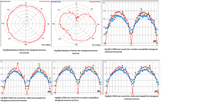
For V0 or V1: Vmax =0.1, Vmin=0.0003 So, VSWR=(Vmax-Vmin)/( Vmax+Vmin)=0.994

Reflection Coefficient, R: (1+VSWR)/(VSWR-1)=-332.33

Return loss=20log[mod(R)]=-50.43 dB

When the antenna is Horizontal:

For V0 or V1: Vmax =0.1584, Vmin=0.0003 So, VSWR=(Vmax-Vmin)/( Vmax +Vmin )=0.9962

Reflection Coefficient, R: (1+VSWR)/ (VSWR-1)= -528.29

Return loss=20log [mod(R)]= -54.45 dB

                                  V. CONCLUSION

The Antenna designed is a wire antenna. The combined effect of different wire section at different orientations give result to the characteristics of the antenna .The antenna configuration was simulated in NEC. At the experiment it was kept at the receiver while a Yagi-Uda antenna was the transmitter . But the antenna structure is not small enough. The VSWR is not exactly 1.00 and it cannot support wideband and multiband application .This problems are expected to be eliminated in near future. The antenna performance will be tried to be more perfect and more versatile .However,  as the antenna is in ISM band, it can be widely used at cellular phone, GSM and Bluetooth communication.

                         ACKNOWLEDGEMENT:

The author of this paper is very much thankful to Antenna Engineering Laboratory of ECE department of KUET, Khulna, Bangladesh for their help in measurement. The author also wishes to thank Mr. Khaled Mahbub Morshed Mahbub and Mr. Abu Md. Numan -Al-Mobin for their kind assistance, review and valuable comments.

                                      REFERENCES:

[1] khaled Mahbub Morshed, Debabrata Kumer Karmokar and Mithul Talukder, “Numerical and Exerimental Annalysis of Imedance Matched      Inverted L and Stair Inverted-L Antenna for 5 GHz WLAN operation”, Journal of Communications, Volume  5 , No. 8,August, 2010

[2] Kheya Banerjee, Abu Md. Numan –Al-Mobin and khaled Mahbub Morshed, “A Compact Loop Type Antenna for Millimeter Band Applications”,12th International conference on Computer and Information Technology (ICCIT 2009), 21-23 December ,2009,Dhaka ,Bangladesh.

[3] Constantine A.  Balanis Antenna Theory Analysis and Design“, John Wiley and Sons Inc., Second Edition ,1982

[4] K. D. Prasad “Antenna and Wave Propagation”, 3rd Edition

[5] John D Kraus, Ronald J Marhefka, Ahmad S Khan ,“Antenna for All Application”, 3rd Edition

[6] www.wikipedia.com

Design And Implementation Of Wire Antenna Of 2.45GHz For Various Application

Abstract:

This report presents wire antenna for Bluetooth, wireless local-area network (WLAN), world interoperability for microwave access (WiMax), S-DMB and Wi-Fi applications. The proposed antenna fed by a 50Ω coaxial line occupies bandwidth is 170MHz (2.37–2.54 GHz) and S11 is less than -10dB, and the measured gain is 2.33 dB at 2.45 GHz. The simulation is employed for optimizing the design parameters, and the simulated results well agree with those of the measured one.

 Introduction:

Recently there is tremendous demand for the development of wireless communication systems for local access networks (WLAN) including Bluetooth, IEEE 802.11a, and 802.11b. This demand has stirred significant renewed interest in antenna design particularly at the ISM bands. Many novel antenna structures for single, dual, or multiple bands have been proposed.

Wi-Fi allows the deployment of local area networks (LANs) without wires for client devices, typically reducing the costs of network deployment and expansion. Spaces where cables cannot be run, such as outdoor areas and historical buildings, can host wireless LANs.As of 2010[update] manufacturers are building wireless network adapters into most laptops. The price of chipsets for Wi-Fi continues to drop, making it an economical networking option included in even more devices. Wi-Fi has become widespread in corporate infrastructures. Different competitive brands of access points and client network-interfaces can inter-operate at a basic level of service. Products designated as “Wi-Fi Certified” by the Wi-Fi Alliance are backwards compatible. “Wi-Fi” designates a globally operative set of standards: unlike mobile phones, any standard Wi-Fi device will work anywhere in the world.

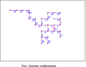
Figure 1 shows the proposed antenna configuration at X-Y plane. Here numeric digit represents the wire number. The length of wire no. 32 is 5mm and rest wires are 12mm long each. The radius of each wire is 1.02626mm.The coaxial feeding is connected at wire no. 19.

antenna structure
antenna structure

Simulation and measured result:

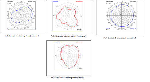
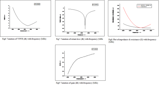
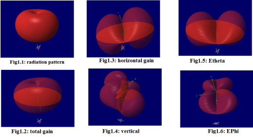
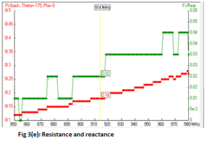
In all figure frequency are calibrated in MHz and plotted in X axis and another parameters are in terms of db.Here Figure 2 and figure 4 represent the simulated radiation pattern at horizontal plane and vertical plane respectively. Figure 3 and figure 5 represent the measured radiation pattern at horizontal plane and vertical plane respectively. In both case we get better output at vertical plane than horizontal plane. S11 parameters are represented by figure 6, 7, 8 and S21 parameter is represented by figure 9.From figure 6 we see that VSWR at center frequency of this antenna (2.45GHz) is 1.00161 and from 2370MHz to 2546MHz VSWR is less than 2.Figure 7 shows that reflection coefficient at 2.45GHz is -61.871 and from 2374MHz to 2540MHz reflection coefficient is less than -10. We can make decision from figure 7 that the bandwidth of this antenna is 170MHz (2370-2540MHz).It is clear to us from figure 8 that the impedance and the radiation resistance or the real part of impedance is almost same around 2.45GHZ which is equal to 50Ω approximately. The impedance is 50.097Ω at 2.45GHz. The gain is fluctuating within a short range (2.3db-2.35db) from 2450MHz to 2550MHz indicated by figure 8.At 2.45GHz the gain is 2.33db.


experimental result
experimental result

Simulation result:

Simulation result

Simulation result

The measured values of VSWR and return loss are given bellow:

      Position               Attenuation                    VSWR           Return loss(dB)
      vertical                     0dB                     1.0038            -54.41
      vertical                    -4dB                     1.0196            -40.24
      vertical                   -8dB                     1.0856            -27.73
      horizontal                     0dB                     1.0095            -46.51
      horizontal                    -4dB                     1.0490            -32.42
      horizontal                   -8dB                     1.1590            -22.67

Table1: Measured VSWR and return loss for various attenuation

The results are relatively close to those predicted by the simulation, but the radiation pattern is distorted, this could be because of the following reasons:

· Reflections – reflections from objects in the room, the walls, floor and ceiling caused significant distortions in the radiation patterns. The plots that were reasonable and which were used for this analysis must still have been degraded by these reflections and since they were not taken into account in the simulation they could account for the discrepancy.

· Construction – During the design process it was found that small changes in the element length or separation can cause large changes in the characteristics of the antenna, therefore any measurement errors introduced during the construction of the antenna could cause the real antenna to perform quite differently to the predicted.

Conclusion: Found that the design process is extremely complicated; with many interacting parameters it is hard to optimize the many characteristics of the antenna simultaneously. The experimental antenna performs relatively similar to the simulated one, the shape of the simulated radiation patterns are of the same form as the experimental, but there are a number of distortions and the frequency shift give the simulation limited real world value. It is clear that the approximations made in the computer model do not allow accurate modeling a real antenna .On the other hand it would also be extremely difficult to design a antenna without simulation software.

Reference:

1. PRINTED STRAIGHT F ANTENNAS FOR  WLAN  AND   BLUETOOTH,   H.Y.   David Yang

Dept. of Electrical and Computer Engineering, Univ. of   Illinois  at  Chicago,Chicago,  IL 60607.

2. A Compact Loop Type Antenna for Bluetooth, S-DMB, Wibro, WiMax, and WLAN Applications

Yong-sun Shin and Seong-Ook Park, Member, IEEE

3.A COMPACT PRINTED HOOK-SHAPED MONOPOLEANTENNAFOR2.4/5-GHz WLAN   APPLICATIONS,  Chi-Hun Lee and  Seong-Ook Park .

Numerical Analysis of Free Space Multiband Wire Antenna for GSM

Application

Name:Biswajit Barua(0709022) & Adnan Hossain Abin(0709014)

E-mail: biswajitbarua100@yahoo.com , abin_ece2k7@yahoo.com

Student of Dept. of Electronics and Communication Engineering

Khulna University of Engineering and Technology,Khulna-9203,Bangladesh


Abstract:

This project presents a triple band (i.e. centered at 900MHz, 1800MHz & 2100MHz) supported wire antenna which is applicable for mobile antenna & Wi-Max operation. This antenna is simulated in software named 4NEC2 in which the antenna is designed and different parameter is measured. For 900MHz centered frequency, this antenna supports a bandwidth of 64MHz from 868 MHz to 932 MHz. For 1800MHz centered frequency, this antenna supports a bandwidth of 88MHz from 1748 MHz to 1836 MHz. For 2100MHz centered frequency, this antenna supports a bandwidth of 22MHz from 2089 MHz to 2111 MHz. The impedance, Voltage standing wave ratio(VSWR), reflection

coefficient, gain and other parameter are perfectly simulated for this antenna which makes its performance better.

Keyword:

GSM based multiband wire antennas necessity and application.

Introduction:

Mobile phone networks are living through times of unprecedented growth in the subscriber base and the number of services being offered. At  the same time operators are encountering  growing pressures from planners and environmental groups. At present the industry needs smaller and less conspicuous based stations with reduced unit cost, all achieved with no compromise in performance.

The pressure on spectrum in the 900MHz band has led to the grant of license to operate in multiband such as 900MHz band, 1800MHz band,  2100MHz band. In some countries where 1800MHz operators have faced difficulties in providing sufficient coverage in less populated rural areas , some 900MHz spectrum has been made available to allow coverage to be extended at lower cost.  2100MHZ band spectrum is used in modern countries. This band is not supported in Bangladesh. When an operator is adding an additional band, the cost of implementation must be held to a minimum, and, the planning problems must be effectively managed. The effectiveness of the existing network must not be compromised.

In general, where the operator is adding a new frequency band to an existing network, the most important consideration is to maintain the same performance in the existing band. Some compromise may be acceptable on the newly introduced band. This is especially true where the new band is to be introduced to increase capacity for existing network services. Where the objective of the operator is to overlay a new network carrying alternative services, the antenna requirement is different, as closely matched coverage may be more important.

However, these frequency band spectrums are also used in wireless local area network (WLAN) & Worldwide Interoperability for Microwave Access (WIMAX) application.

Antenna structure:

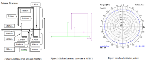
The antenna is made of a combination of F-shaped & L-shaped structure. Total length of wire used in this antenna, is 42.358cm which is small compared to any other wire antenna structure. This antenna is constructed in xz pane. So it stands vertically with its y plane. It is so stable with its feeding or sma connector because its small structure.

Multiband wire antenna structure,Multiband antenna structure in 4NEC2,simulated radiation pattern

In this graph, the voltage standing wave ratios are 1.078 at 900MHz frequency, 1.103 at 1800MHz frequency & 1.073 at 2100 MHz frequency. These values are constant for a small range of their individual frequency spectrum. In these frequency ranges, antenna radiates most highly.

simulation result

simulation result

simulation result1

simulation result1

The value of reflection coefficient in this antenna are -28.5db for 900MHz, -26.2db for 1800MHz & -29.1db for 2100MHz. it is much greater than the standard value. So performance is much better in this case.The gain of any antenna is inversely proportional to the bandwidth of the antenna. For 900MHz band, the bandwidth of the antenna is 64MHz. so the value of gain is certainly increased to 1.54 which is greater than the standard value. But this gain is decreased in 1800MHz band with a 88MHz bandwidth.The impedance of this antenna are 47.41 ohm, 50.2ohm & 50.25 ohm for 900MHz, 1800MHz & 2100MHz band which is nearly equal to the its standard value 50 ohm. So this antenna reduces its power loss and gives maximum radiation in free space.

Measured Result:

This antenna is made of three frequency band spectrum i.e. 900MHz band, 1800MHz & 2100 MHz. But in these frequency spectrum is not supported in the laboratory for the measurement of performance. Only two frequency spectrums are supported in laboratory. That is 914MHz & 2450MHz. We consider the 914MHz for the measurement as nearest value of 900MHz band. Few performance parameters may fluctuate from the simulation result.The radiation pattern is almost circular. It can be changed with some parameter. If there are no obstacles in the certain range of its radiation, then it gives more circular and accurate radiation pattern. If there are obstacles, the radiation pattern would be distorted. Radiation pattern also depends upon its position of radiation. Some antenna radiates properly at vertical position and some at horizontal.


experimental result

experimental result

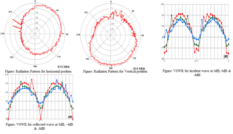
The measured value of voltage standing wave ratio for incident wave is different from simulated value. The value of VSWR at 0dB is 1.0130. it is increased at -4dB & -8dB respectively. The value at that level is 1.0355 & 1.1250 which is larger than the simulated value.

 1.0001. it is increased at -4dB & -8dB respectively. The value at that level is 1.0282& 1.0513. which is larger than the simulated value.

Wire NO

segment

Radius

1

2

1.026mm

2

8

1.026mm

3

2

1.026mm

4

1

1.026mm

5

1

1.026mm

6

1

1.026mm

7

2

1.026mm

8

9

1.026mm

9

3

1.026mm

10

9

1.026mm

11

5

1.026mm

12

8

1.026mm

13

1

1.026mm

Table: wire segment and radius for all wires

The wire used in this antenna, is made by copper. The radius of this wire is 1.026mm which is usually known as 12 gauges wire. The antenna fading is given at wire number five which length is 1.2cm and the antenna fading is in the middle of that wire.

Conclusion:

 The main objective of designing this triple band antenna is to omit the band limitation problem in mobile phone network. This antenna is designed in software named 4NEC2. So all parameter should be maintained. In 4NEC2, it is made at x-z axis. So it works better in its vertical position rather than horizontal position. The major limitation of this antenna is gain which can be reduced by changing its parameter. Such as  micro strip antenna gives more gain than wire antenna. So in modern world it is used more because of its performance. But wire antenna are also used for its low cost and simplicity.

 Reference:

[1].  Khaled Mahbub Morshed, Debabrata Kumar Kormokar and Abu Md. Numan-Al-Mobin  ‘Numerical analysis of impedance matched Inverted-L antennas for Wi-Fi operations’ , proceeding of 2009 12th ICCIT, 2009, Dhaka , Bangladesh.

[2]. Kheya Banerjee, Abu Md. Numan-Al-Mobin  and Khaled Mahbub Morshed ‘ A Compact Loop Type Antenna for Millimeter Band Applications’  proceeding of 2009 12th ICCIT, 2009, Dhaka , Bangladesh.

[3]. http://www.lemosint.com/radiometrix/radiometrix_details.php?itemID=216

[4]. http://cellphonesafety.wordpress.com/category/914-mhz/

[5]. Antenna & wave propagation-K.D. Prasad

[6]. Antenna theory-Balanis

[7]. Internet.

[8]. Wikipidia

[9]. Encyclopedia


2.45GHz FREE SPACE ANTENNA FOR WLAN APPLICATION.

MD.BILLAL HOSSAIN

Electronics and Communication Engineering, KUET, Khulna-9203.

Email:billal.0709018@gmail.com


Abstract:

In this project our goal is to design an antenna that operates in 2.45GHz by using 4NEC software for WLAN application. We use 12 gauge copper wire which is available and cheap in cost and 50Ω coaxial connector (SMA). Our designed antenna has a bandwidth at about 250MHz.It support 2350MHz to 2600MHz within VSWR at about 1.

Keyword: ISM band, WLAN.

Introduction:

The industrial, scientific and medical (ISM) radio bands were originally reserved internationally for the use of radio frequency (RF) energy for industrial, scientific and medical purposes other than communications. The ISM bands are defined by the ITU-R in 5.138, 5.150, and 5.280 of the Radio Regulations. Individual countries’ use of the bands designated in these sections may differ due to variations in national radio regulations. Because communication devices using the ISM bands must tolerate any interference from ISM equipment, these bands are typically given over to uses intended for unlicensed operation, since unlicensed operation typically needs to be tolerant of interference from other devices anyway. The ISM bands defined by the ITU-R are Frequency range [Hz] 2.400–2.500 GHz Center frequency [Hz] 2.450 GHz.

WLAN stands for wireless local area network.WLAN are nowadays widely used. The 802.11 workgroup currently documents use in three distinct frequency ranges, 2.4 GHz, 3.6 GHz and 4.9/5.0 GHz bands.[1]. IEEE 802.11 is a set of standards for implementing wireless local area network (WLAN) computer communication in the 2.4, 3.6 and 5 GHz frequency bands. They are created and maintained by the IEEE LAN/MAN Standards Committee (IEEE 802). The base current version of the standard is IEEE 802.11-2007.There are four types of protocol are in WLAN they are 802.11a, 802.11b, 802.11g, 802.11n. There are 14 channels designated in the 2.4 GHz range spaced 5 MHz apart (with the exception of a 12 MHz spacing before Channel 14). As the protocol requires 25 MHz of channel separation, adjacent channels overlap and will interfere with each other. Consequently, using only channels 1, 6, 11, and 14 are recommended to avoid interference. All of those 14 channels are in-between 2412MHz to 2484MHz.So we need consider this thing for antenna design for WLAN application.


Antenna design:

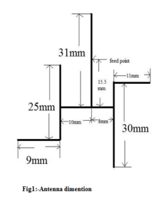
The physical dimension of designed antenna is showed bellow figure. We use 12 gauge copper wires for design this antenna.

Antenna dimention

Antenna dimention

Fig1:-Antenna dimention

Simulated value:

Simulated value

Simulated value

Simulated value

Simulated value

Simulated value

Simulated value

Measured value:

measured value

measured value

Table1: of measured VSWR:

Position

Attenuation(dB)

VSWR

Reflection coefficient(dB)

Horizontal

0

1.0057

-25.391

Horizontal

-4

1.0490

-16.211

Horizontal

-8

1.1933

-9.48137

Vertical

0

1.0187

-20.313

Vertical

-4

1.1669

-11.133

Vertical

-8

1.1933

-10.547

Result analysis:

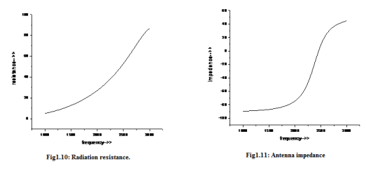
From table we can see that the VSWR for horizontal position at 0dB is 1.0057 and our simulated value for the frequency 2.45GHz is 1.0221 so it is nearly to our simulated value again standard VSWR for a antenna is 1 so this value also near to the standard value. From the radiation pattern from figure 1.3 we can see that radiation pattern for horizontal position is circular and our measured value as shown in figure 1.13 is almost like simulated result but not in exactly same. From simulated result figure 1.7 shows reflection coefficient. In 2.45GHz frequency reflection coefficient value is -39dB and we need reflection coefficient less then -12dB and from table1 we come to see that for horizontal position our measured reflection coefficient is -25dB so from this view our antenna is have an acceptable reflection coefficient value.Table1 shows reflection coefficient for different attenuation. For vertical position our calculated reflection coefficient is -20.313dB this is also acceptable range. From figure 1.9 we can see that the gain of our antenna at our desired frequency is 2.13dB so gain is also well. From figure 1.10 and 1.11 we can see our simulated radiation resistance and impedence.From that we can see that our resistance is 49.7301ohm and impedance is 48.7414ohm so it is suitable doe coaxial connector such as SMA connector.

Conclusion:

In this project we are able to design an antenna which operates in ISM band 2.45GHz and all of parameter are acceptable and have a good performance. This antenna also can be used in other application such as radio telemetry, Bluetooth.

Reference:

  1.  IEEE 802.11-2007: Wireless LAN Medium Access Control (MAC) and Physical Layer (PHY) specifications
  2. CONSTANTINE A.BALANIS “ANTENNA THEORY ANALYSIS AND DESGN” second edition.
  3. D.M. Pozar, Microwave Engineering, 2nd Ed., NewYork: John Wiley & Sons, 1998
  4. W.-C. Su and K.-L. Wong; “Internal PIFAs for
  1. K.D.PRASAD “ANTENNA & WAVE PROPAGATION” edition 2009-20010.

UMTS/WLAN/WiMAX multi-network operation

for a USBdongle”, Microwave Opt. Tech. Lett,

Vol. 48, No. 11, pp.2249-2253, 2006

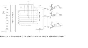
In the long corridors of the hotels, unnecessary electricity is consumed on the lights. Ideally when no one is there the lights should be switched off. As the person passes from one end to the other the corresponding.

circuit diagram for reduced power of coridoor light

circuit diagram for reduced power of coridoor light

Figure 6.8 Circuit diagram of the system for auto switching of lights in the corridor

lights should be switched on so that he or she will be guided toward the corridor end. This problem is solved by using arrays of pairs of IR LEDs and phototransistor throughout the corridor placed at equal interval as shown in the block schematic. The array of IR LEDs are in a continuous emitting mode. The corresponding IR phototransistors are aligned at 45◦ for maximizing sensitivity. Value of the resistance (1MΩ to 470Ω) connected to the collector of the phototransistor decides its sensitivity. When the IR link breaks due to the person passing the corridor, a low to high going transition is detected by the port 0 lines. The corresponding bulbs connected to port 1 are made ON and OFF so as to light the corridor as the person makes his way to the other end.

*********************************************************
Program Source Code

mail:billal.0709018@gmail.com

cell:+8801816166360
*********************************************************
#include <REG52.H> /∗ special function register declarations ∗/
#include <stdio.h>
/∗ for the intended 8051 derivative ∗/
sbit sensor1= P0∧0; /∗ Output from the 8 sensors is connected to
the port pins of the port 0 ∗/
sbit sensor2= P0∧1;
sbit sensor3= P0∧2;
sbit sensor4= P0∧3;

sbit sensor5= P0∧4;
sbit sensor6= P0∧5;
sbit sensor7= P0∧6;
sbit sensor8= P0∧7;
/∗ Connecting the relays to on/off the power to the port 1 ∗/
sbit RL1= P1∧0;
sbit RL2= P1∧1;
sbit RL3= P1∧2;
sbit RL4= P1∧3;
sbit RL5= P1∧4;
sbit RL6= P1∧5;
sbit RL7= P1∧6;
sbit RL8= P1∧7;
void main (void) // Main function
{P0=0x00;
P1=0x00;
while(1)
{if(sensor1==1) // Sense the first sensor
RL1=1; // If its output is high then switch the relay on
else if (sensor2==1) // otherwise check the second sensor.
{RL1=0; // Off relay 1 and on relay 2
RL2=1;
}
else if (sensor3==1)
{RL3=1;
RL2=0;
}else if (sensor4==1)
{RL4=1;
RL3=0;
}else if (sensor5==1)

{RL5=1;
RL4=0;
}else if (sensor6==1)
{RL6=1;
RL5=0;
}else if (sensor7==1)
{RL7=1;
RL6=0;
}else if (sensor8==1)
{RL8=1;
RL7=0;
}}
}
*********************************************************
A useful device for taking the audience poll regarding a lecture or any other issue is described in this application. This device will be passed on to each and every member of the audience one by one. A message appears on the LCD as regards to whether the lecture is satisfactory or otherwise. Accordingly the user has to press key 1 or 2. The poll will be displayed as soon as key 3 is pressed.This is simple circuit for electronics voting system.We can design a big system if we simply modify the programming.

microcontroller voting machine

microcontroller voting machine

Figure 6.7 Circuit diagram of unit for anonymous voting

######################################################################

Program Source Code

contact: billal.0709018@gmail.com

call:+8801816166360

######################################################################

#include <REG52.H> /∗ special function register declarations ∗/
#include <stdio.h> /∗ for the intended 8051 derivative ∗/
sbit RS = P2∧0; // LCD control signals
sbit RW = P2∧1;
sbit EL = P2∧2;
sbit BU = P2∧4; // Buzzer as a output
sbit R1 = P0∧0; // Hex keypad connections

sbit R2 = P0∧1;
sbit R3 = P0∧2;
sbit R4 = P0∧3;
sbit C1 = P0∧4;
sbit C2 = P0∧5;
sbit C3 = P0∧6;
sbit C4 = P0∧7;
void Delay(int);
void INIT(void);
void ENABLE(void);
void LINE(int);
int keyb(void);
void LINE(int i) /∗ Function for the LCD display line selection
and giving the respective commands to LCD ∗/
{ if (i==1) { RS=0;
RW=0;
P1=0x80;
ENABLE();
RS=1;
}else
{RS=0;
RW=0;
P1=0xC0;
ENABLE();
RS=1;
}
}
void delay(int k) // Delay function
{int i,j;
for (j=0;j<k+1;j++){ for (i=0;i<100;i++);
}}

void ENABLE(void) // Function to Enable the LCD. Give high
to low pulse on EL.
{EL=1;
delay(1);
EL=0;
delay(1);
}
void INIT(void) /∗ Initialization of the LCD by sending the
commands sequentially ∗/
{ RS=0;
RW=0;
EL=0;
P1 = 0x38;
ENABLE();
ENABLE();
ENABLE();
ENABLE();
P1 = 0x06;
ENABLE();
P1 = 0x0E;
ENABLE();
P1 = 0x01;
ENABLE();
}
int keyb(void) // Keyboard scanning function. Checks which
key is pressed.
{int key=0;
C1=1;
C2=1;
C3=1;
C4=1;
R1=0;
R2=1;
R3=1;
R4=1;

if (C1==0) key = 1;
if (C2==0) key = 2;
if (C3==0) key = 3;
if (C4==0) key = 4;
R1=1;
R2=0;
R3=1;
R4=1;
if (C1==0) key = 5;
if (C2==0) key = 6;
if (C3==0) key = 7;
if (C4==0) key = 8;
R1=1;
R2=1;
R3=0;
R4=1;
if (C1==0) key = 9;
if (C2==0) key = 10;
if (C3==0) key = 11;
if (C4==0) key = 12;
R1=1;
R2=1;
R3=1;
R4=0;
if (C1==0) key = 13;
if (C2==0) key = 14;
if (C3==0) key = 15;
if (C4==0) key = 16;
return(key);
}
void main(void)
{ char vote1[]=“Lecture is satisfactory: Press 1”; /∗ Array for the
characters to display
on the LCD. ∗/
char vote2[]=“Lecture is not up to mark: Press 2”;

char ∗p; // Pointer to point the next character in the
array
int j,i;
INIT();
LINE(1);
j=0;
while(1)
{ /∗ When key 1 is pressed matter raised is ok ∗/
j=0;
j = keyb();
if (j==1){ p=&vote1; // Memory address define to array and defined a pointer to
point that data.
for(i=0;i<17;i++)
{if(i==0) // Display the data on the first line on the LCD
screen
LINE(1);
if(i==8)
LINE(2); // Display the data on the second line on the LCD screen
P1= ∗p++; // Pointer is incremented and the data pointed by pointer
is sent on the port 1.
ENABLE();
Delay(200);
}if (j==2){ /∗ If key 2 is pressed then the vote is for the matter
is not enough ∗/
p=&vote2;
for(i=0;i<17;i++)
{if(i==0)
LINE(1);
if(i==8)
LINE(2); // Display the content on line 2
P1= ∗p++; // Increment the pointer
ENABLE();
Delay(200);
}}
}}} //End of the main
*********************************************************