PSO Algorithm to Maximize the Function F (X, Y, Z)

This is a matlab project for Engineering student.

*Initialize the values for initial position a, b, c, d, e

**Initialize the next positions decided by the individual swarms as a’, b’, c’
d’ and e’

*** Global decision regarding the next position is computed as follows.
Compute f (a’, b, c, d, e), f (a, b’, c, d, e), f (a, b, c’, d, e), f (a, b, c, d’, e)
and f (a, b, c, d, e’). Find minimum among the computed values. If f (a’,
b, c, d, e) is minimum among all, the global position decided regarding
the next position is a’. Similarly If f (a, b’, c, d, e) is minimum among all,
b’ is decided as the global position regarding the next position to be
shifted and so on. Let the selected global position is represented ad
‘global’

****Next value for a is computed as the linear combination of ‘a’ , (a’-a) and
(global-a) (ie)

• nexta = a+ C1 * RAND * (a’ –a) + C2 * RAND * (global –a )
• nextb = b+ C1 * RAND * (b’ –b) + C2 * RAND * (global –b)
• nextc = c+ C1 * RAND * (c’ –c) + C2 * RAND * (global –c )
• nextd = d+ C1 * RAND * (d’ –d) + C2 * RAND * (global –d )
• nexte = e+ C1 * RAND * (e’ –e) + C2 * RAND * (global –e )

*****Change the current value for a, b, c, d and e as nexta, nextb, nextc, nextd
and nexte

******If f (nexta, b, c, d, e) is less than f (a’, b, c, d, e) then update the value for
a’ as nexta, otherwise a’ is not changed.

If f (a, nextb, c, d, e) is less than f (a, b’, c, d, e) then update the value for
b’ as nextb, otherwise b’ is not changed

If f (a, b, nextc, d, e) is less than f (a, b, c’, d, e) then update the value
for c’ as nextc, otherwise c’ is not changed

If f (a, b, c, nextd, e) is less than f (a, b, c, d’, e) then update the value
for d’ as nextd, otherwise d’ is not changed

If f (a, b, c, d, nexte) is less than f (a, b, c, d, e’) then update the value
for e’ as nexte, otherwise e’ is not changed

*******Repeat the steps 3 to 6 for much iteration to reach the final decision.
The values for ‘c1’,’c2’ are decided based on the weightage given to
individual decision and global decision respectively.
Let Δa(t) is the change in the value for updating the value for ‘a’ in t
iteration, then nexta at (t+1)th iteration can be computed using the following
formula. This is considered as the velocity for updating the position of the
swarm in every iteration.

nexta (t+1) =a (t) +Δa(t+1)

where
Δa(t+1) = c1 * rand * (a’ –a ) + c2 * rand * ( gl obal –a ) +w(t)* Δa(t)

Decision taken in the previous iteration is also used for deciding the next
position to be shifted by the swarm. But as iteration increases, the
contribution of the previous decision is decreases and finally reaches zero in
the final iteration.

%%%%%%%%%%%%%%%matlab_code%%%%%%%%%%%%%%%%

**** psogv .m

function [value]=psogv(fun,range,ITER)
%psogv.m
%Particle swarm algorithm for maximizing the function fun with two variables x
%and y.
%Syntax
%[value]=psogv(fun,range,ITER)
%example
%fun=’f1′
%create the function fun.m
%function [res]=fun(x,y)
%res=sin(x)+cos(x);
%range=[-pi pi;-pi pi];
%ITER is the total number of Iteration
error=[];
vel1=[];
vel2=[];
%Intialize the swarm position
swarm=[];
x(1)=rand*range(1,2)+range(1,1);
y(1)=rand*range(2,2)+range(2,1);
x(2)=rand*range(1,2)+range(1,1);
y(2)=rand*range(2,2)+range(2,1);
%Intialize weight
w=1;
c1=2;
c2=2;
%Initialize the velocity
v1=0;%velocity for x
v2=0;%velocity for y
for i=1:1:ITER
[p,q]=min([f1(fun,x(2),y(1)) f1(fun,x(1),y(2))]);
if (q==1)
capture=x(2);
else
capture=y(2);
end

v1=w*v1+c1*rand*(x(2)-x(1))+c2*rand*(capture-x(1));
v2=w*v2+c1*rand*(y(2)-y(1))+c2*rand*(capture-y(1));
vel1=[vel1 v1];
vel2=[vel2 v2];
%updating x(1) and y(1)
x(1)=x(1)+v1;
y(1)=y(1)+v2;
%updating x(2) and y(2)
if((f1(fun,x(2),y(1)))<=(f1(fun,x(1),y(1))))
x(2)=x(2);
else
x(2)=x(1);
end;
if((f1(fun,x(1),y(2)))<=(f1(fun,x(1),y(1))))
y(2)=y(2);
else
y(2)=y(1);
end
error=[error f1(fun,x(2),y(2))];
w=w-w*i/ITER;
swarm=[swarm;x(2) y(2)];
subplot(3,1,3)
plot(error,’-‘)
title(‘Error(vs) Iteration’);
subplot(3,1,1)
plot(swarm(:,1),’-‘)
title(‘x (vs) Iteration’);
subplot(3,1,2)
plot(swarm(:,2),’-‘)
title(‘y (vs) Iteration’);
pause(0.2)
end
value=[x(2);y(2)];

***** f1.m

function [res]=f1(fun,x,y);
s=strcat(fun,'(x,y)’);
res=eval(s);

%%%%%%%%%%%%%%%%%%%%%%%%%%%%%%%%%%%%%%%

refference: E.S. Gopi . Algorithm Collections for Digital Signal Processing
Applications Using Matlab.

All Rights Reserved
© 2007 Springer

module dflipflop( q,qbar,d,clk,clear);
input d,clk,clear;
output q,qbar;
wire s,sbar,r,rbar,cbar;
assign cbar= ~clear;
assign sbar = ~(rbar & s),
  s = ~(sbar & cbar & (~clk)),
  r = ~(rbar & (~clk) & s),
  rbar = ~(r & cbar & d);
assign q = ~(s & qbar),
  qbar = ~(q & r & cbar);
endmodule

module dflipflop0();
wire q0,qbar0;
reg d0,clk0,clear0;
initial
begin
clk0=1;
clear0=1;
d0=1;

#10 clk0=1;
#00 clear0=0;
#00 d0=1;

#20 clk0=0;
#00 clear0=0;
#00 d0=1;

#30 clk0=0;
#00 clear0=1;
#00 d0=1;
end
dflipflop s(.clear(clear0),.clk(clk0),.q(q0),.qbar(qbar0),.d(d0));
endmodule

module Add_Sub_4_bit (
output [3: 0] S,
output C,
input [3: 0] A, B,
input M
);
wire [3: 0] B_xor_M;
wire C1, C2, C3, C4;
assign C = C4; // output carry
xor (B_xor_M[0], B[0], M);
xor (B_xor_M[1], B[1], M);
xor (B_xor_M[2], B[2], M);
xor (B_xor_M[3], B[3], M);
// Instantiate full adders
full_adder FA0 (S[0], C1, A[0], B_xor_M[0], M);
full_adder FA1 (S[1], C2, A[1], B_xor_M[1], C1);
full_adder FA2 (S[2], C3, A[2], B_xor_M[2], C2);
full_adder FA3 (S[3], C4, A[3], B_xor_M[3], C3);
endmodule
module full_adder (output S, C, input x, y, z); // See HDL Example 4.2
wire S1, C1, C2;
// instantiate half adders
half_adder HA1 (S1, C1, x, y);
half_adder HA2 (S, C2, S1, z);
or G1 (C, C2, C1);
endmodule
module half_adder (output S, C, input x, y); // See HDL Example 4.2
xor (S, x, y);
and (C, x, y);
endmodule
module t_Add_Sub_4_bit ();
wire [3: 0] S;
wire C;
reg [3: 0] A, B;
reg M;
Add_Sub_4_bit M0 (S, C, A, B, M);
initial #100 $finish;
initial fork
#10 M = 0;
#10 A = 4’hA;
#10 B = 4’h5;
#50 M = 1;
#70 B = 4’h3;
join
endmodule

BCD stands for binary coded decimal. It is speatial types of 4(quard bit) bit representation of a number. Such as if a number in decimal 12 it is represented by BCD as 00010010.

7 segment display have so many application. Though now a day digital display LCD, LED used widely but for low price application 7 segment display widely used. For students project ( MCU related project) it is widely used. BCD to seven segment decoder are designed in verilog HDL. Core are given bellow.

module Seven_Seg_Display_V2001 (
output reg [6: 0] Display,
input [3: 0] BCD
);
// abc_defg
parameter BLANK = 7’b000_0000;
parameter ZERO = 7’b111_1110; // h7e
parameter ONE = 7’b011_0000; // h30
parameter TWO = 7’b110_1101; // h6d
parameter THREE = 7’b111_1001; // h79
parameter FOUR = 7’b011_0011; // h33
parameter FIVE = 7’b101_1011; // h5b
parameter SIX = 7’b101_1111; // h5f
parameter SEVEN = 7’b111_0000; // h70
parameter EIGHT = 7’b111_1111; // h7f
parameter NINE = 7’b111_1011; // h7b
always @ (BCD)
case (BCD)
0: Display = ZERO;
1: Display = ONE;
2: Display = TWO;
3: Display = THREE;
4: Display = FOUR;
5: Display = FIVE;
6: Display = SIX;
7: Display = SEVEN;
8: Display = EIGHT;
9: Display = NINE;
default: Display = BLANK;
endcase
endmodule
module t_Seven_Seg_Display_V2001 ();
wire [6: 0] Display;
reg [3: 0] BCD;
parameter BLANK = 7’b000_0000;
parameter ZERO = 7’b111_1110; // h7e
parameter ONE = 7’b011_0000; // h30
parameter TWO = 7’b110_1101; // h6d
parameter THREE = 7’b111_1001; // h79
parameter FOUR = 7’b011_0011; // h33
parameter FIVE = 7’b101_1011; // h5b
parameter SIX = 7’b001_1111; // h1f
parameter SEVEN = 7’b111_0000; // h70
parameter EIGHT = 7’b111_1111; // h7f
parameter NINE = 7’b111_1011; // h7b
initial #120 $finish;
initial fork
#10 BCD = 0;
#20 BCD = 1;
#30 BCD = 2;
#40 BCD = 3;
#50 BCD = 4;
#60 BCD = 5;
#70 BCD = 6;
#80 BCD = 7;
#90 BCD = 8;
#100 BCD = 9;
join
Seven_Seg_Display_V2001 M0 (Display, BCD);
endmodule

Decoder is a digital circuit that can select a line according to the input pattern. Decoder can be used as a control unit for a MCU,processor etc. 4 to 16 line decoder verilog code arr given bellow.

module decoder(x,y,z,w,e,d);
input  w,x,y,z,e;
output [15:0]d;
assign d[0]=  (~x) & (~y) &(~z) & (~w) & (e) ;
assign d[1]=  (~x) & (~y) &(~z) & (w) & (e) ;
assign d[2]=  (~x) & (~y) &(z) & (~w) & (e) ;
assign d[3]=  (~x) & (~y) &(z)  & (w) & (e) ;
assign d[4]=  (~x) & (y) &(~z) & (~w) & (e) ;
assign d[5]=  (~x) & (y) &(~z)  & (w) & (e) ;
assign d[6]=  (~x) & (y) &(z)  & (~w) & (e) ;
assign d[7]=  (~x) & (y) &(z)  & (w) & (e) ;

assign d[8]=  (x) & (~y) &(~z) & (~w) & (e) ;
assign d[9]=  (x) & (~y) &(~z) & (w) & (e) ;
assign d[10]= (x) & (~y) &(z) & (~w) & (e) ;
assign d[11]= (x) & (~y) &(z)  & (w) & (e) ;
assign d[12]= (x) & (y) &(~z) & (~w) & (e) ;
assign d[13]= (x) & (y) &(~z)  & (w) & (e) ;
assign d[14]= (x) & (y) &(z)  & (~w) & (e) ;
assign d[15]= (x) & (y) &(z)  & (w) & (e) ;

endmodule

module decoder2();
reg x0,y0,z0,w0,e0;
wire [15:0]dd;

initial
begin
e0=0;
x0=0;
y0=1;
z0=0;
w0=1;

#10 e0=1;
#00 x0=0;
#00 y0=0;
#00 z0=0;
#00 w0=0;

#10 x0=0;
#00 y0=0;
#00 z0=1;
#00 w0=1;

#10 x0=0;
#00 y0=1;
#00 z0=0;
#00 w0=0;

#10 e0=0;
end
decoder s(.d(dd),.e(e0),.x(x0),.y(y0),.z(z0),.w(w0));
endmodule

The project aims to build an automated system that will alert the food assistance staff that a customer has arrived for service. It can also be used for a housewife who wants to know if someone has arrived at the gate. An IR transceiver pair has been used for detecting the presence of the person at the front desk. The program polls the port pins and displays a message on the LCD that “Someone is arrived” as well as activates a buzzer. The system is also ideal for a bank cashier.

front desk notifier

front desk notifier

Program Source Code
*********************************************************
#include <REG52.H> /∗special function register declarations∗/
/∗ for the intended 8051 derivative ∗/
sbit RS = P2∧0;
sbit RW = P2∧1;
sbit EN = P2∧2;
sbit IN= P2∧4; /∗input from the sensor present at gate ∗/
sbit Buzz=P2∧5; // output indication to housewife∗/
void delay(int); /∗ Stop Exection with Serial Intr. ∗/
void INIT(void);
void ENABLE(void);
void LINE(int);

void LINE(int i){ if (i==1) { RS=0;
RW=0;
P1=0x80;
ENABLE();
RS=1;
}else
{RS=0;
RW=0;
P1=0xC0;
ENABLE();
RS=1;
}
}
void delay()
{int i,j;
for (j=0;j<10;j++){ for (i=0;i<100;i++);
}}
void ENABLE(void)
{EN=1;
delay();
EN=0;
delay();
}
void INIT(void) // Initialization of the LCD by giving the proper
commands.
{ RS=0;
RW=0;
EN=0;
P1 = 0x38; // 2 lines and 5∗7 matrix LCD.

ENABLE();
ENABLE();
ENABLE();
ENABLE();
P1 = 0x06; //Shift cursor to left
ENABLE();
P1 = 0x0E; // Display ON, Cursor Blinking
ENABLE();
P1 = 0x01; // Clear display Screen.
ENABLE();
}
void main (void){ char code array[] = ”Some is there on the gate”;
char code array1[]=”No one is there on the gate”;
int b,j;
Buzz=0;
while(1)
INIT();
LINE (1);
{ if( IN==1) // some one is there if in = 1
{ Buzz=1; // switch on the buzzer to indicate some
one is there on gate
for (b=0;b<30;b++)
{if (b==8)
LINE(2);
P1=array[b];
ENABLE();
}
RS=0;
P1=0x01;
ENABLE();
RS=1;
LINE(1);
for (b=16;b<33;b++)
{ if (b==24)

LINE(2);
P1=array1[b];
ENABLE();
}
}else // display no one there on gate
{for (b=0;b<30;b++)
{if (b==8)
LINE(2);
P1=array1[b];
ENABLE();
} RS=0;
P1=0x01;
ENABLE();
RS=1;
LINE(1);
for (b=16;b<33;b++)
{ if (b==24)
LINE(2);
P1=array1[b];
ENABLE();
}}}}
*********************************************************

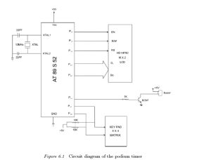
The podium timer is designed for giving the indication of timeout for a series of timed speeches. The 4 × 4 hex keyboard enables the user to set the time and start the timer. Once the timer is ON, it constantly indicates the time on the LCD. Before 3 minutes (which is also programmable) of actual timeout, it gives an indication by means of short beep. As soon as the time set is elapsed, the unit enables the buzzer indicating the timeout.

podium timer

podium timer

Program Source Code
*********************************************************
#include <REG52.H> /∗ special function register declarations ∗/
/∗ for the intended 8051 derivative ∗/
sbit RS = P2∧0;
sbit RW = P2∧1;
sbit EL = P2∧2;
sbit buzz = P2∧3;
sbit R1 = P3∧0;
sbit R2 = P3∧1;
sbit R3 = P3∧2;
sbit R4 = P3∧3;
sbit C1 = P3∧4;
sbit C2 = P3∧5;
sbit C3 = P3∧6;

sbit C4 = P3∧7;
void Delay(int);
void INIT(void);
void ENABLE(void);
void LINE(int);
int keyb(void);
void settime(void);
void starttimer(void);
void check timeout(int);
int settime1=10;
void settime(void)
{
int ten pos=0, unit pos=0;
while(!(ten pos=keyb()));
while(!(unit pos=keyb()));
P1=(((ten pos))+0x30);
ENABLE();
P1=((unit pos)+0x30);
ENABLE();
Delay(2000);
settime1= ten pos∗10 + unit pos;
}
void starttimer()
{int set temp= settime;
check timeout(3); //check for the warning timeout default 3 min before
end time
check timeout(set temp);
set temp–;
P1=(((set temp)/10)+0x30);
ENABLE();
P1=((set temp/10)%10+0x30);
ENABLE();

Delay(2000);
}
void check timeout(g)
{if(g == 3)
{buzz=1;
Delay(100);
buzz=0;
}if (g == 0)
buzz=1;
Delay(400);
buzz=0;
}void main(void)
{ char test[]=“Podium timer”;
char code set msg[]=“1-> set time”;
char code start msg[]=“2-> start timer”;
char ∗p;
int j;
INIT();
LINE(1);
p=&test;
for(j=0;j<17;j++)
{if(j==0)LINE(1);
if(j==8)LINE(2);
P1= ∗p++;
ENABLE();
Delay(200);
}while(1){
RS = 1;
p=&set msg;
for(j=0;j<17;j++)
{

if(j==0)LINE(1);
if(j==8)LINE(2);
P1= ∗p++;
ENABLE();
Delay(200);
}
RS = 1;
p=&start msg;
for(j=0;j<17;j++)
{if(j==0)LINE(1);
if(j==8)LINE(2);
P1= ∗p++;
ENABLE();
Delay(200);
}
j=0;
j=keyb();
if(j>0);
if(j==1){ settime();
}if(j==2){
starttimer();
}}}
void Delay(int k)
{int i,j;
for (j=0;j<k+1;j++){ for (i=0;i<100;i++);
}}
void ENABLE(void)
{EL=1;
Delay(1);

EL=0;
Delay(1);
}void LINE(int i){ if (i==1) { RS=0;
RW=0;
P1=0x80;
ENABLE();
RS=1;
}else
{RS=0;
RW=0;
P1=0xC0;
ENABLE();
RS=1;
}
}void INIT(void) // Initialization of the LCD by giving the proper
commands.
{ RS=0;
RW=0;
EL=0;
P1 = 0x38; // 2 lines and 5∗7 matrix LCD.
ENABLE();
ENABLE();
ENABLE();
ENABLE();
P1 = 0x06; //Shift cursor to left
ENABLE();
P1 = 0x0E; // Display ON, Cursor Blinking
ENABLE();
P1 = 0x01; // Clear display Screen.
ENABLE();
}
int keyb(void){ int key=0;
C1=1;

C2=1;C3=1;C4=1;R1=0;R2=1;R3=1;R4=1;
if (C1==0) key = 1;
if (C2==0) key = 2;
if (C3==0) key = 3;
if (C4==0) key = 4;
return(key);
}
*********************************************************
Figure 6.1 Circuit diagram of the podium timer
6.2 Application

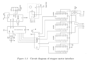
The circuit diagram of the packet-based stepper motor interface is asshown in Figure. The commands to be emulated from the Hyper-Terminal and the corresponding control action are given in the program source code. The interface is based on UN2003 driver popularly used for many stepper motor control applications. It is a 7-bit, 50V 500mA TTL-input NPN Darlington driver. The drivers does not need power supply; the VDD pin is the common cathode of the seven integrated protection diodes.

stepper motor controll interface

stepper motor controll interface

Program Source Code
******************************************************
#include<REG52.h>
unsigned char mot[4] = {0x0a,0x06,0x05,0x09};
unsigned char run, clkwise;
int interpret, mode, count;
char packet[5]; /∗p[0] is control char∗/
char index; /∗others may contain data last must contain end char,
i.e., ‘z’ ∗/
void init(void);
void delay (int m);
void init()
{TMOD=0x20;
TH1=0xFD; /∗select baud rate 9600∗/
SCON=0x50;
TR1=1; /∗ start timer∗/
}

void main(void)
{int k=0;
char i;
init(); ES=1; EA=1;
run=1;
clkwise = 1;
for (i=0;i<5;i++){ packet[i]=0;
}index=0;
interpret=0;
while(1)
{while(mode==0){ /∗continues rotation∗/
while(run==1)
{if(clkwise==1){ for (i=0;i<4 ; i++) /∗ clkwise dir∗/
{ P0= mot [i];
delay(1000);
}} else
{for (i=3;i>=0 ; i−−) /∗anticlkwise dir∗/
{ P0= mot [i];
delay(1000);
}
}}
}}
while(mode==1) /∗number of step’s given by user∗/
{while((run==1)&&(count>0))
{if(clkwise==1){ for ( i=0;i<4 ; i++)
{ P0= mot [i];
delay(1000);
}
}

else
{for ( i=3;i>=0 ; i−−)
{P0= mot [i];
delay(1000);
}}
count−−;
}
}
} void delay (int m)
{ int z;
z=m;
while (m>0)
{ m−−;}
}
void serialisr() interrupt 4
{ unsigned char y;
char i;
RI=0;
y=SBUF; /∗ contents of buffer
in y∗/
TI=0; SBUF=y; while (!TI);TI=0; /∗similtaneusly
display∗/
packet[index]=y;
index++;
if (y==‘Z’) { interpret =1; /∗ indicates end of packet∗/
index = 0;
}

else interpret = 0;
if (interpret==1)
{

switch(packet[0])
{

case ‘S’:
run=0;
break;

case ‘R’:
run=1;
break;
case ‘A’:
clkwise=0;
break;
case ‘C’:
clkwise=1;
break;
case ‘D’:
if (packet[1]==’0’)
mode=0;
break;
case ‘E’:
if (packet[1]==’1’)
mode=1;
break;
case ‘F’: /∗variable size packet∗/
count=(packet[3]-0x30)+((packet[2]-0x30)∗10)+((packet[1]-
0x30)∗100);
break; /∗packet[3]=units……….∗/
} for (i=0;i<5;i++){ packet[i]=0;
}interpret=0;
}
}

******************************************************


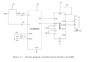
The circuit diagram of the packet-based LED interface is as shown in Figure 5.1. The commands to be emulated from the HyperTerminal and the corresponding control action is given in the program source code.

packet based interface for LED

packet based interface for LED

Program Source Code
*******************************************************
/∗ Displaying different LED sequence pattern based on the packet
received ∗/
#include<REG52.h>

unsigned char led;
int interpret;
char packet[4];
char index;
void init(void);
void delay (int m);
void init()
{TMOD=0X20;
TH1=0xFD; /∗select baud rate 9600∗/
SCON=0x50;
TR1=1; /∗ start timer∗/
}
void main(void)
{int k=0;
char i;
init();
ES=1;
EA=1; // Global interrupt bit enabled
led=0xff;
for (i=0;i<4;i++){ packet[i]=0;
}
index=0;
interpret=0;
while(1)
{
{P0= led;
delay(1000);
}
}} void delay (int m) // Function for the Delay.
{ int z;
z=m;

while (m>0)
{ m−−;}
}
void serialisr() interrupt 4
{ unsigned char y;
char i;
RI=0;
y=SBUF; // write the data in srial buffer.
TI=0;
SBUF=y; // read the data from serial buffer.
while (!TI); // Check the flag
TI=0;
packet[index]=y;
index++;
if (y==‘z’)
{interpret =1;
index = 0;
}else interpret = 0;
if (interpret==1)
{switch(packet[0])
{case ‘A’:
led=0x55; // 01010101
break;
case ‘B’:
led=0x33;
break;
case ‘C’:
led=0x55;
delay(100);
led=0x33;
break;
case ‘D’:
led=0x00;

delay(100);
led=0x02;
delay(100);
led=8;
delay(100);
led=16;
delay(100);
led=16;
delay(100);
led=32;
delay(100);
led=64;
delay(100);
led=256;
delay(100);
break;
}
for (i=0;i<4;i++)
{ packet[i]=0;
}interpret=0;
}
}
*******************************************************

This program can show your desired text message in LCD screen.The application of this field is vast.This project can be used for customer care,for lighting,for publish a notice or any other application.This is very simple application of micro-controller and cost is very low.The main component of this project is only a micro-controller .So keep enjoy it….

Program Source Code
*********************************************************
#include <REG52.H>
sbit RS = P2∧0; // Control signal RESET of the LCD connected
to pin P2.0
sbit RW = P2∧1; // Write (RW) Signal pin connected to pin P2.1
sbit EN = P2∧2; // Enable (EN) LCD control signal connected to
pin P2.2
int i;
void delay(void); // Delay function
void INIT(void); // Function for the commands to Initialization of
the LCD
void ENABLE(void); // Function for the commands to enable the LCD
void LINE(int); /∗ Function for the commands to choose the line for
displaying the characters on the LCD ∗/
void LINE(int i) // start of LINE function
{ if (i==1)
{RS=0; // first make the reset signal low
RW=0; // make RW low to give commands to the LCD
P1=0x80; // force cursor to beginning of the first line
ENABLE(); // enable the LCD
RS=1;
}else
{RS=0;
RW=0;
P1=0xC0; // force cursor to beginning of the second line
ENABLE();
RS=1;
}
}

void delay() // Invoking the delay function.
{int j;
for (j=0;j<10;j++)
{for (i=0;i<100;i++);
}}
void ENABLE(void) // Invoking the enable function
{ EN=1; // Give high to low pulse to Enable the LCD.
delay();
EN=0;
delay();
}
void INIT(void) // Initialization of the LCD by giving the proper
commands.
{ RS=0;
RW=0;
EN=0;
P1 = 0x38; // 2 lines and 5∗7 matrix LCD.
ENABLE();
ENABLE();
ENABLE();
ENABLE();
P1 = 0x06; //Shift cursor to left
ENABLE();
P1 = 0x0E; // Display ON, Cursor Blinking
ENABLE();
P1 = 0x01; // Clear display Screen.
ENABLE();
}
void main (void)
{
char code dis[] = “We Thank Springer Publishers”;
char code dis2[] = “From Authors”; // Array of characters
to be display.

char ∗p; // Pointer to point the data in the array.
int j,x;
while(1)
{for (x=1;x<3;x++)
{
INIT();
LINE(1); // Display on the line 1 of the LCD.
if (x==1)
{p=&dis; // point the character address from the array “dis” where
it is stored.
}else
{p=&dis2; // Point the Character address from the “dis2” where it
is stored/
}for (j=0;j>8;j++){ P1= ∗p++; // Increment the pointer by 1.
ENABLE();
} LINE(2); // Display the second array on the second line on the LCD.
}}
}
*********************************************************