Design of 16bit Magnitude Comparator using VLSI
Md. Imran khan, 4th year student of ECE department, KUET
Abstract—This paper proposed a magnitude comparator that cans comparate two 16 bit binary sequence and give decision which one is larger. It can also detect the situation when these two numbers are same. Now a day’s magnitude comparator is used in many complicated devices such as CPU, microcontroller ,microcomputer etc. op- amps also do this same works perfectly but it is used in analog domain. So magnitude comparator is must for comparison in digital domain.
| T |
1. Introduction
he comparison of two numbers is an operation that determines whether one number is greater than, less than, or equal to the other number. A magnitude comparator is a combinational circuit that compares two numbers A and B and determines their relative magnitudes. The outcome of the comparison is specified by three binary variables that indicate whether A > B, A = B, or A < B.
Generally, magnitude comparators are digital circuits (IC’s) which have two ports which accept, and latch two 8 or 16 bit binary numbers and have three single bit outputs: “Greater than, less than, and equal.”I guess the “importance” is twofold. First, as you can use a single IC you simplify the hardware, but more importantly, for certain operations, they can be invaluable. One simple use would be comparing the output of a free running digital counter to some fixed number. This fixed number, if derived from user adjustable binary hex switches, would allow control based on some adjustable terminal count. For instance, if the counter also fed into a D to A converter, and use the magnitude comparator to compare the two numbers, you now have a user adjustable ramp which can further be used with analog comparators to trigger many sorts of analog systems and also acts as a digital divider.
2.Model Description
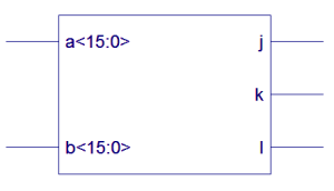
This design proposed a 16 bit magnitude comparator which have two input lines and three output terminal.Two input sequnce comes to terminal a and terminal b.Depending of these two values any of three terminal will be active.Only one output terminal will be active at a time.If bit sequence of a is higher then k terminal will be active. If bit sequence of b is higher then j terminal will be active. If bit sequence of a and b is same then l terminal will be active. In order to manually determine the greater of two binary numbers, we inspect the relative magnitudes of pairs of significant digits, starting from the most significant bit, gradually proceeding towards lower significant bits until an inequality is found.
Fig1:Basic model of magnitude comparator
3. Operation
The circuit for comparing two n-bit numbers has 22” entries in the truth table and becomes too cumbersome, even with n = 3. On the other hand, as one may suspect. a comparator circuit possesses a certain amount of regularity. Digital functions that possess an inherent well-defined regularity can usually be designed by means of an algorithm—a procedure which specifies a finite set of steps that, if followed, give the solution to a problem. We illustrate this method here by deriving an algorithm for the design of a four-bit magnitude comparator. The algorithm is a direct application of the procedure a person uses to compare the relative magnitudes of two numbers. Consider two numbers, A and B, with four digits each. Write the coefficients of the numbers in descending order of significance:
A=A3 .A2 .A1 .A0
B=B3 .B2 .B1 .B0
Each subscripted letter represents one of the digits in the number. The two numbers are equal if all pairs of significant digits are equal: A3 = B3, A2 = B2, A1 = B1 and A0 = B0. When the numbers are binary, the digits are either 1 or 0, and the equality of each pair of bits can be expressed logically with an exclusive-NOR function as
Xi=Ai.Bi+Ai’.Bi’
Where x = I only if the pair of bits in position i are equal (i.e., if both are 1 or both are 0).
The equality of the two numbers A and B is displayed in a combinational circuit by an output binary variable that we designate by the symbol (A = B). This binary variable is equal to 1 if the input numbers, A and B, are equal, and is equal to 0 otherwise. For equality to exist, all xi variables must be equal to 1, a condition that dictates an AND operation of all variables:
(A = B) = x3x2x1x0
The binary variable (A = B) is equal to I only if all pairs of digits of the two numbers are equal. To determine whether A is greater or less than B, we inspect the relative magnitudes of pairs of significant digits, starting from the most significant position. If the two digits of a pair are equal. We compare the next lower significant pair of digits. The comparison continues until a pair of unequal digits is reached. If the corresponding digit of A is 1 and that of B is 0, we conclude that A > B. If the corresponding digit of A is 0 and that of B is 1, we have A < B. The sequential comparison can be expressed logically by the two Boolean functions
(A > B) = A3B3’ + x3A2B2 + x3x2A1B1 + x3x2x1A0B0’
(A<B)= A3’B3+ x3A2’B2 + x3x2A1’B1’ + x3x2x1A0’B0’
4. Synthesized Result
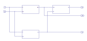
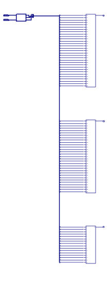
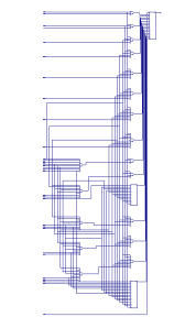
Using Xlink software synthesis is done.1st figure shows four blocks. Among them smallest block is represented in figure 2 and the biggest one is represented in figure 3.The three blocks represented AND gate in figure 3.
Simulation is done in verilogger pro software.Simulation result shows that when the value of a terminal is higher than terminal b then k terminal is in logic 1 state. But when the value of b terminal is higher than terminal a then j terminal is in logic 1 state. Figure shows that l terminal is always 0 state because the input value of a and b is not same in the timing diagram.
6. Application
Comparators are used in a central processing units (CPU) and microcontrollers. Examples of digital comparator include the CMOS 4063 and 4585 and the TTL 7485 and 74682-’89.One could create a temperature control for example using a sensor as one input but calculated in the digital domain, possibly with some microcomputer to make decisions. once used a very similar setup using two daisy-chained magnitude comparators in a telemetry system where the comparators monitored a counter which counted digital telemetry pulses and thus was the “memory of the number of pulses and were used as a trigger for a set point alarm or maximum allowable user adjusted limit. As mentioned above, they can also be used to make a digital divider. For instance, using a free-running counter as one comparator input, and user switches as the other, you will get an “Equal to” signal for every x counts / y user input count. Very simple way to divide counts by any amount. It’s not so much “what’s the importance” as that fully depends on the application, but rather the versatility and all the clever things one can use them for. It can be designed more complex uses for them but I did do some pretty cool, very specialized things which would have been difficult to do without using the magnitude comparators. Only your imagination limits the cool things you can use them for. Basically, Analog circuits like op-amps compare strictly in the analog domain. Magnitude comparators allow comparing purely in the digital domain. Combining the digital, D-to-A converters, and op-amps allows doing both simultaneously, if needed by the application.
7. Limitation
It needs to much logical gate to implement this circuit. So complexity is higher. As a result processor needs too much time to execute it. The operation cannot be seen in normal FPGA board due to much terminal declaration. Future work can be done about reduction of complexity of this circuit.
8. Conclusion
The gate implementation of the three output variables just derived is simpler than it seems because it involves a certain amount of repetition. The unequal outputs can use the same gates that are needed to generate the equal output. The timing diagram of the 16-bit magnitude comparator is shown in Fig. 5. The three outputs are generated with exclusive-NOR circuits and are applied to an AND gate to give the output binary variable (A = B). The other two outputs use the x variables to generate the Boolean functions listed previously. This is a multilevel implementation and has a regular pattern. The procedure for obtaining magnitude comparator circuits for binary numbers with more than four bits is obvious from this example.
9. Reference
1.http:wiki.answers.com/Q/What_is_the_importance_of_magnitude_comparator
2. M. Morris Mano, Emeritus Profemr of Computer Engineering Callfornio State University, Los Angeles, Digital Design 4th Edition.
3. Professor Barry Paton, Dalhousie University; Fundamentals of Digital Electronics
###########################################################
Test bench verification and verilog HDL code .
############################################################
module q( a, b, j,k,l);
input [15:0] a;
input [15:0] b;
output j;
output k;
output l;
wire [30:1]r;
wire[47:0]x;
wire [15:0]a;
wire[15:0]b;
block stage0(a[0],b[0],x[0],x[1],x[2]);
block stage1(a[1],b[1],x[3],x[4],x[5]);
block stage2(a[2],b[2],x[6],x[7],x[8]);
block stage3(a[3],b[3],x[9],x[10],x[11]);
block stage4(a[4],b[4],x[12],x[13],x[14]);
block stage5(a[5],b[5],x[15],x[16],x[17]);
block stage6(a[6],b[6],x[18],x[19],x[20]);
block stage7(a[7],b[7],x[21],x[22],x[23]);
block stage8(a[8],b[8],x[24],x[25],x[26]);
block stage9(a[9],b[9],x[27],x[28],x[29]);
block stage10(a[10],b[10],x[30],x[31],x[32]);
block stage11(a[11],b[11],x[33],x[34],x[35]);
block stage12(a[12],b[12],x[36],x[37],x[38]);
block stage13(a[13],b[13],x[39],x[40],x[41]);
block stage14(a[14],b[14],x[42],x[43],x[44]);
block stage15(a[15],b[15],x[45],x[46],x[47]);
assign r[1]=x[3]&x[1];
assign r[2]=x[5]&x[1];
assign r[3]=x[6]&x[4]&x[1];
assign r[4]=x[8]&x[4]&x[1];
assign r[5]=x[9]&x[7]&x[4]&x[1];
assign r[6]=x[11]&x[7]&x[4]&x[1];
assign r[7]=x[12]&x[10]&x[7]&x[4]&x[1];
assign r[8]=x[14]&x[10]&x[7]&x[4]&x[1];
assign r[9]=x[15]&x[13]&x[10]&x[7]&x[4]&x[1];
assign r[10]=x[17]&x[13]&x[10]&x[7]&x[4]&x[1];
assign r[11]=x[18]&x[16]&x[13]&x[10]&x[7]&x[4]&x[1];
assign r[12]=x[20]&x[16]&x[13]&x[10]&x[7]&x[4]&x[1];
assign r[13]=x[21]&x[19]&x[16]&x[13]&x[10]&x[7]&x[4]&x[1];
assign r[14]=x[23]&x[19]&x[16]&x[13]&x[10]&x[7]&x[4]&x[1];
assign r[15]=x[24]&x[22]&x[19]&x[16]&x[13]&x[10]&x[7]&x[4]&x[1];
assign r[16]=x[26]&x[22]&x[19]&x[16]&x[13]&x[10]&x[7]&x[4]&x[1];
assign r[17]=x[27]&x[25]&x[22]&x[19]&x[16]&x[13]&x[10]&x[7]&x[4]&x[1];
assign r[18]=x[29]&x[25]&x[22]&x[19]&x[16]&x[13]&x[10]&x[7]&x[4]&x[1];
assign r[19]=x[30]&x[28]&x[25]&x[22]&x[19]&x[16]&x[13]&x[10]&x[7]&x[4]&x[1];
assign r[20]=x[32]&x[28]&x[25]&x[22]&x[19]&x[16]&x[13]&x[10]&x[7]&x[4]&x[1];
assign r[21]=x[33]&x[31]&x[28]&x[25]&x[22]&x[19]&x[16]&x[13]&x[10]&x[7]&x[4]&x[1];
assign r[22]=x[35]&x[31]&x[28]&x[25]&x[22]&x[19]&x[16]&x[13]&x[10]&x[7]&x[4]&x[1];
assign r[23]=x[36]&x[34]&x[31]&x[28]&x[25]&x[22]&x[19]&x[16]&x[13]&x[10]&x[7]&x[4]&x[1];
assign r[24]=x[38]&x[34]&x[31]&x[28]&x[25]&x[22]&x[19]&x[16]&x[13]&x[10]&x[7]&x[4]&x[1];
assign r[25]=x[39]&x[37]&x[34]&x[31]&x[28]&x[25]&x[22]&x[19]&x[16]&x[13]&x[10]&x[7]&x[4]&x[1];
assign
r[26]=x[41]&x[37]&x[34]&x[31]&x[28]&x[25]&x[22]&x[19]&x[16]&x[13]&x[10]&x[7]&x[4]&x[1];
assign r[27]=x[42]&x[40]&x[37]&x[34]&x[31]&x[28]&x[25]&x[22]&x[19]&x[16]&x[13]&x[10]&x[7]&x[4]&x[1];
assign r[28]=x[44]&x[40]&x[37]&x[34]&x[31]&x[28]&x[25]&x[22]&x[19]&x[16]&x[13]&x[10]&x[7]&x[4]&x[1];
assign
r[29]=x[45]&x[43]&x[40]&x[37]&x[34]&x[31]&x[28]&x[25]&x[22]&x[19]&x[16]&x[13]&x[10]&x[7]&x[4]&x[1];
assign r[30]=x[47]&x[43]&x[40]&x[37]&x[34]&x[31]&x[28]&x[25]&x[22]&x[19]&x[16]&x[13]&x[10]&x[7]&x[4]&x[1];
assign l=x[46]&x[43]&x[40]&x[37]&x[34]&x[31]&x[28]&x[25]&x[22]&x[19]&x[16]&x[13]&x[10]&x[7]&x[4]&x[1];
assign j=x[0]|r[1]|r[3]|r[5]|r[7]|r[9]|r[11]|r[13]|r[15]|r[17]|r[19]|r[21]|r[23]|r[25]|r[27]|r[29];
assign k=x[2]|r[2]|r[4]|r[6]|r[8]|r[10]|r[12]|r[14]|r[16]|r[18]|r[20]|r[22]|r[24]|r[26]|r[28]|r[30];
endmodule
module block(f,g,m,n,o);
input f,g;
output m,n,o;
assign m=(~f)&g;
assign o=(~g)&f;
assign n=~(m|o);
endmodule
module q1();
reg [15:0] a1;
reg [15:0] b1 ;
wire j1,k1,l1;
initial
begin
a1=16’b1111111111111111;
b1=16’b1111111111110000;
#10 a1=16’b1111111111110000;
#0 b1=16’b1111111111111111;#20$stop;end
q s(.a(a1),.b(b1),.j(j1),.k(k1),.l(l1));
endmodule


